Contents
Introduction
With effect from 1 July 2007, colour for identification of conductors in fixed electrical installations will be changed, and the details are shown in Table 1 and the Code of Practice for the Electricity (Wiring) Regulations (CoP).
Table 1 - Change of Cable Colour Code
The change is applicable to all new electrical installations as well as addition & alteration to existing electrical installations. Existing installations with cables adopting the old cable colour code will not be affected.
A Working Group on the Review of Cable Colour Code in Hong Kong comprising members from the trade and industry was established in year 2003 to study the cable colour change issue in Hong Kong. In mid 2004, the Working Group proposed to adopt the new cable colour code in Hong Kong. The change was then endorsed by the Electrical Safety Advisory Committee in September 2004.
The new cable colour code complies with the requirements of relevant national and international standards (such as IEC 60446, EN 60446, BS EN 60446 and BS 7671) and has been adopted by the majority of the western countries (e.g. UK, France, Germany, Spain, Netherlands, Portugal etc.).
Existing Colour & New Colour
Implementation
Figure 2 - Implementation Schedule
The new colour code may be used for those electrical installation works commencing on-site on or after 1 July 2007. For installation works commencing on-site from 1 July 2007 to 30 June 2009 (i.e. the 2-year grace period), either the new or the existing old colour code, but NOT both, can be used. For installation works commencing on-site on or after 1 July 2009, only the new colour code should be used.
Precautions
In the new colour code, the black core will be changed from neutral to phase and the blue core from phase to neutral (see Table 1). Wrong connection of these cores will lead to increased risk, leading to possible electrical accidents and short circuiting, in particular during the transition period. To ensure electrical safety, it is recommended not to conduct, whenever practicable, works on "LIVE" installations at any cable colour change interfaces. Where serious inconvenience would arise from isolating electrical circuits for works at the cable colour change interfaces, adequate safety precautions should be taken to avoid danger from "LIVE" working conditions (see Code 4 of the CoP for details).
Installation Guides - New Installation
The old cable colour code, i.e. red, yellow and blue for phase conductors and black for the neutral conductor, are to be replaced by the new one, i.e. brown, black and grey for phase conductors and blue for the neutral conductor, as specified in Table 1. Circuits for new installations should be wired in new colour coded cables (see examples in Figures 2(a) and 2(b)).
For a single phase installation, only the brown colour should be used to identify a phase conductor, irrespective of whether it is connected to the L1, L2 or L3 phase. For a room /flat /unit taking single phase electricity supply from a multi-phase power supply source, only brown (phase) and blue (neutral) coloured cables should be used.
Installation Guides - Extensions, Alterations or Repair to an Existing Installation
Figure 3 - Warning Notice 5.1 Warning Notice
Warning Notice
Where cables in new colour code are installed in an existing installation with old colour coded cables, a yellow warning notice in both English and Chinese (see Figure 3) should be displayed at or close to the nearest upstream distribution board (e.g. main switchboard, sub-main distribution board or consumer unit) of the affected installation. The warning notice should be durable and securely fixed in position. Letters and characters should be legible. The characters '?p?s' and 'Caution' should not be less than 10 mm in height. Other characters should not be less than 5 mm in height. The warning notice should have a minimum size of 100mm (width) x 75mm (height).
Single-phase installation
Extension, alteration or repair to an existing single-phase installation should be wired in the colour of brown (for phase conductor), blue (for neutral conductor), and green-and-yellow (for protective conductor) as specified in Table 1.
a. Existing cables adopting red for phase and black for neutral
If the existing single phase installation has adopted the red colour for phase conductor and black for neutral conductor (i.e. correctly identified), both the new and old colour coded cables are considered unambiguously marked. It is therefore not necessary to provide additional marking / label at the interface between new and old colour coded cables (see Figure 4).
Figure 4 - Extension, alteration and repair to an existing single phase installation, where existing phase conductors are identified by red colour b. Existing cables adopting either yellow or blue for phase and black for neutral
Proper durable and legible labels or coding (such as cable ties, sleeves, ferrules etc.) should be provided on the new cables near the cable termination interface (see Figures 5(a) to 5(d)). The above provision is to standardize the wiring work for incorrectly identified cables and to avoid any possibility of mistaking the old "blue" (phase) cable as the new "blue" (neutral) cable.
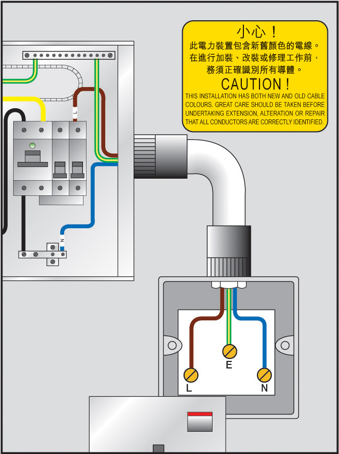
Figure 5 (a) - Addition of new colour coded cables to an existing MCB board where phase conductor is identified by yellow colour
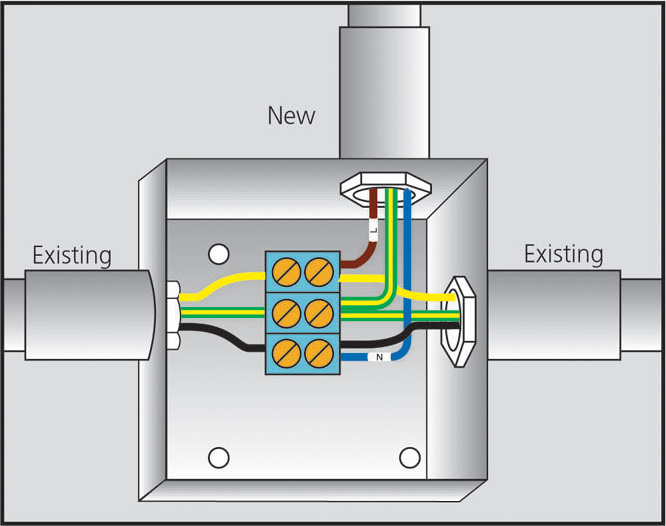
Figure 5 (b) - Extension, alteration and repair to an existing single phase installation where phase conductor is identified by yellow colour 
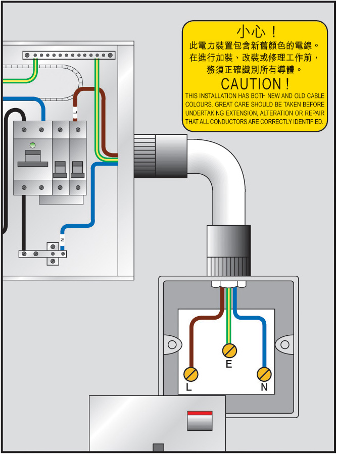
Figure 5 (c) - Addition of new colour coded cables to an existing MCB board where phase conductor is identified by blue colour
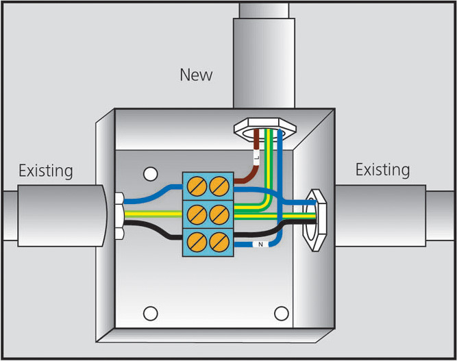
Figure 5 (d) - Extension, alteration and repair to an existing single phase installation where phase conductor is identified by blue colour
Three-phase installation
Extension, alteration or repair to an existing 3-phase installation should be wired in the new colour code of brown/ black/ grey/ blue/ (green-and-yellow) as specified in Table 1.
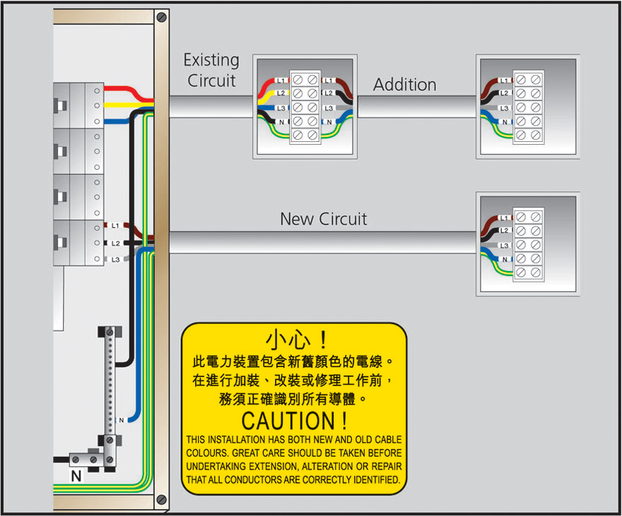
At the wiring interface, both the new and old phase and neutral conductors should be fitted with proper, durable and legible identification marked in L1, L2, L3 and N (Figure 6).
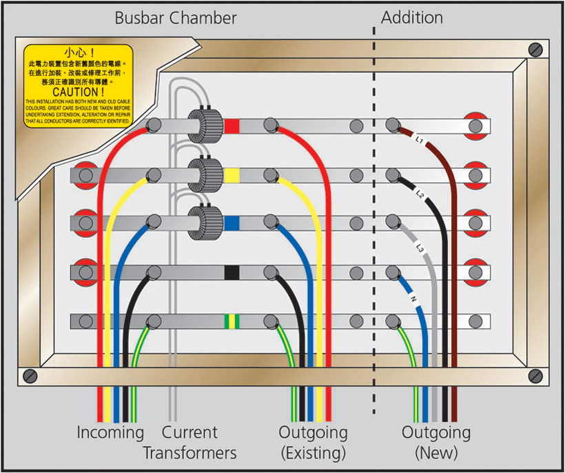
Figure 6 - Extensions, alterations or repairs to an existing three-phase installation For the interface between new and old colour coded cables at a busbar chamber for an existing three-phase installation, an acceptable means of identification is illustrated in Figure 7.
Figure 7 - Interface between new and old colour coded cables at a busbar chamber for an existing three-phase installation
Contact Information
Contact Information
Electricity Legislation Division, EMSD, 3 Kai Shing Street, Kowloon, Hong Kong
1823
2895 4929
info@emsd.gov.hk
Installation Guidelines